I’ll teach you to write your own Metal shaders, and utilise them in your own SwiftUI apps. Since many of you won’t have touched C++ or graphics code before, I’m going to try to explain all the basics, while keeping succinct.
Your end of the bargain? You’ve got to code along.
In a matter of hours, you’ll be firing lightning-fast graphical effects out of your fingertips like a pixellated Palpatine.
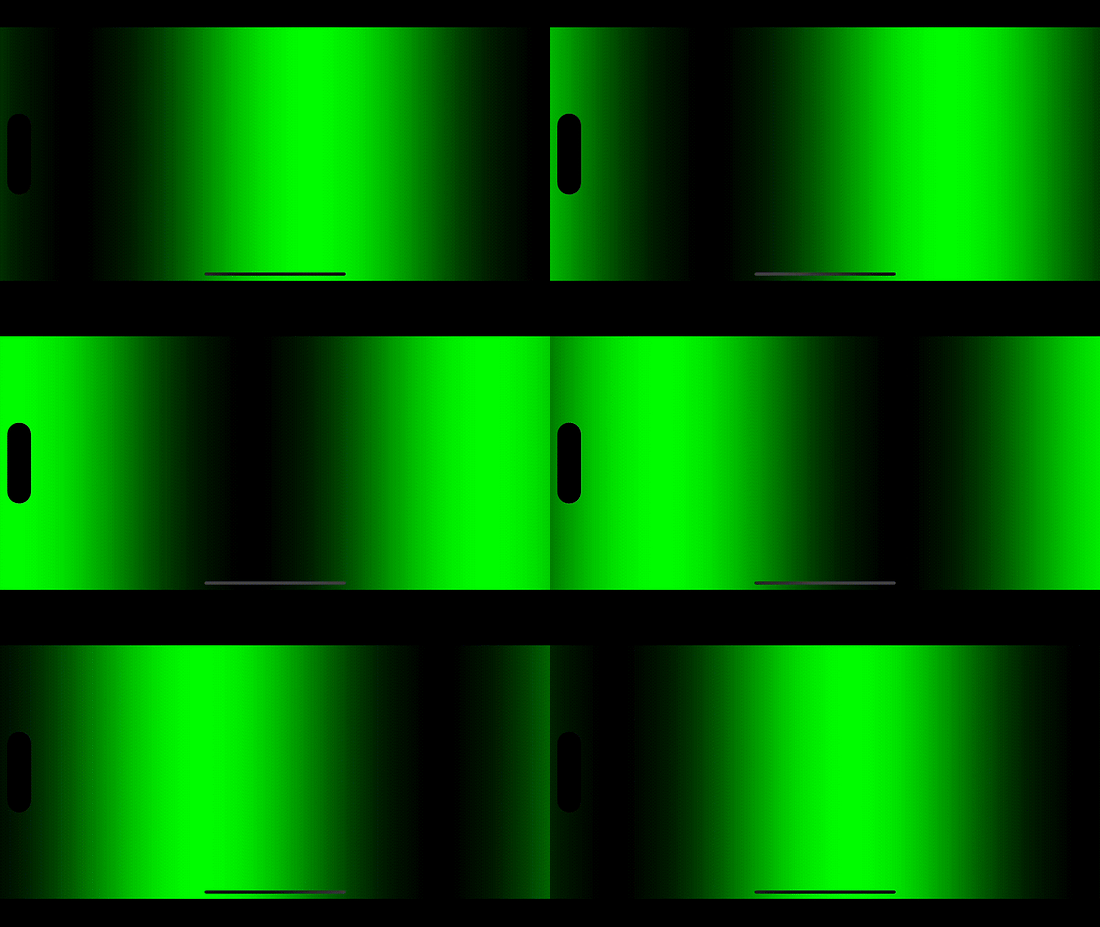
Here’s a few of the effects we’ll learn to create (all smooshed together in one view)
I’ll link to specific commit hashes in my sample project at the start of each section, so you can skip around without getting lost. We’re going to create Metal shaders from scratch, one building block at a time.
In the early 2010s, GPUs were improving fast : their performance was pulling way ahead of CPUs. Hardware-accelerated graphics frameworks like OpenGL, which utilised the GPU, were bottlenecked by their driver software which still ran on the CPU.
To remedy this problem, Apple created Metal , a graphics framework which could interface directly with the graphics chip.
Metal is usually used by creators of game engines and machine learning researchers to process ultra-parallelised floating point operations. Most developers, even those making 3D games, aren’t using Metal directly.
There are a few important definitions to learn before we get started:
Shaders are tiny functions that run on the GPU to handle rendering.
Fragment shaders color the individual pixels on a screen (these are what we use in SwiftUI).
Vertex shaders map 3D vector coordinates onto 2D screens (these power 3D games).
Metal Shading Language is the C++-based language we use to write shaders.
Why is Metal so fast?
Shaders are extremely efficient because of one word.
Parallelisation.
Fragment shader functions run individually for each on-screen pixel. The GPU is built specifically to handle massively parallel floating-point operations like these. These work so well because each pixel can be calculated independently of the others.
For the uninitiated , a floating-point operation, or FLOP, is a mathematical function that involves adding, subtracting, multiplying, and dividing floating-point numbers, a.k.a. ‘floats’.
Let’s do some quik mafs to understand how many parallel operations we can run on the GPU.
The iPhone 15 Pro Max, with 3.61 million pixels refreshing at 120Hz, will therefore require 430,000,000x floating-point operations per second, where x is the number of floating-point operations per shader function.
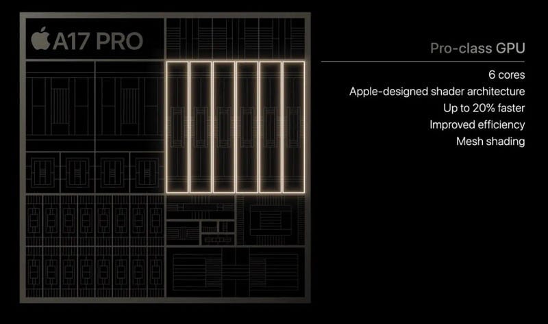
Hot off the press: The GPU in the Apple A17 Pro SoC has 6 cores, each running at 1.4GHz, and each with an insane 128 shading units (each core can utilise these simultaneously . This is known as superscalar architecture). The GPU can run at 2.15 teraflops , that is, 2.15 trillion floating point operations per second.
The maths works out as 2.15 TFLOPS = 1.4GHz * 6 Cores * 128 Shading Units * 2 . I reckon the extra factor of 2 at the end is due to some good pipelining and branch prediction.
This means that the GPU can happily handle 5000 floating point operations on each fragment shader , that is, per pixel, per frame!
Apple’s marketing materials for the new A17 Pro GPU . From Apple / ZDNET
Okay, I’ll stop selling you phones. Let’s look at some code.
We start with an Xcode project targeting iOS 17+ . The shiny new shader view modifiers are tied to this OS version. To ensure the screenshots look nice in long-form article format, I’ve locked the orientation to Landscape-right. Finally, I’ve set up a few folders to keep our shaders organised:
/ColorEffects
/DistortionEffects
/LayerEffects
/MoreEffects
Each folder contains a View extensions file that defines our view modifiers, and their own .metal shaders file.
Other than that, I’ve left the default App and ContentView files intact.
Here’s the plan: Our workflow will involve creating a simple view, producing a view modifier that uses shaders, and writing the most basic possible shader. We’ll build up increasingly complex shaders as we understand more and more.
Part II: Color Effect
Setting up our View
If you skipped straight here, here’s the commit hash to kick us off with learning colorEffect. Clone it and join in the fun!
Our journey into shaders begins with a basic SwiftUI view, a simple white canvas, with a custom modifier attached:
struct ContentView: View {
    var body: some View {
        Color.white
            .edgesIgnoringSafeArea(.all)
            .colorShader()
    }
}
I used .edgesIgnoringSafeArea(.all) to make my screenshots look better.
The colorShader() function can be turned into a simple view modifier wrapping the colorEffect modifier and our shader (that we’re about to make). We place it inside View+ColorEffect.
Creating a ViewModifier accomplishes a few things . First and foremost, it keeps our call site neat by encapsulating all our shader-aware code. It also means we can store state in the modifier struct itself (that becomes important later) and allows SwiftUI to make optimisations under the hood.
The iOS 17 colorEffect modifier takes a Shader as an argument. This is a reference to a function in a shader library, and also accepts any arguments you want to pass along (we’ll see those later on). ShaderLibrary itself is another struct that uses dynamic member lookup to locate a ShaderFunction that you specify in your .metal files.
The Metal Template
Now the real fun begins. We’ll be writing our first shadersto set the color of each pixel. Let’s go to ColorEffects/Color.metal and inspect the template.
#include <metal_stdlib>   // 1
using namespace metal;    // 2
The template contains 2 things:
#include <metal_stdlib> to import the Metal Standard Library, which contains many commonly used mathematical operations for shaders.
using namespace metal; which tells the compiler to use the metalnamespace in this file, which cleans up our code, as we can write float2 instead of metal::float2 for position and half4 instead of metal::half4 for color.
Our First Shader Function
Here’s the function signature for our first shader function.
How did I know to write this? Am I a C++ genius? A metal god?
No . Eeven better. I read the docs.
If you option-click on the colorEffect modifier, the documentation appears in all its glory:
Discussion: For a shader function to act as a color filter it must have a function signature matching: [[ stitchable ]] half4 name(float2 position, half4 color, args...). The function should return the modified color value.
Finally, before we add our own logic, we should get familiar with the types we’re working with:
float2 is avector of 2 floating-point numbers . That is, it stores two separate numbers together in the one type. Here, it’s used to represent the x and y coordinates of on-screen pixels (accessible through dot-syntax).
half4 is a vector of 4 half-width floating-point numbers. Half-width? This means their bits are stored in half as much memory as a float (this is the opposite of a double). This more lightweight type is used used to store the r, g, b, and a values for a color, which can also be accessed via dot-syntax.
Understanding Color
Metal shaders perform their operations separately on every individual pixel. The GPU is designed to run these massively parallel calculations without breaking a sweat.
Let’s start with the most basic colorEffect shader I could come up with: returning the current color of the pixel, without modification.
While this function is basic, there’s a lot to unpack here:
The [[ stitchable ]] declaration does two things. Firstly, it tells the compiler to make the function visible to the Metal Framework API, allowing us to use it in SwiftUI. Secondly, it allows Metal to stitch shaders together at runtime. This means the shader code, and SwiftUI view modifiers themselves, can be used to compose multiple shader effects together in a performant manner on the same views.
half4 color is the return type and our function name. This is the standard function syntax for C-family languages.
float2 position inputs the coordinates of the pixel this shader function is operating on.
The half4 color argument is the starting color of the pixel on which this shader is operating.
return color; is the return statement , the resulting color of the pixel at position. Here, we are just returning the original color without changing anything.
Here’s what we see when we run the code:
Returning each pixel as its original color
Let’s actually implement some more logic into our shader.
The next basic step is to actually modify the color we get; hardcoding a return value:
Returning each pixel as a zeroed-out RGB color , i.e. black
Take a moment to play with the numbers to return any color you like. I was quite partial to using 128.0/255.0 for each component, giving that sweet, sweet Space Grey hue.
Understanding Position
Now let’s find out how to handle pixel position in our colorEffect shader. If you’re starting here, here’s the commit hash that includes the progress so far on the project.
There’s another piece in the Metal puzzle that presents itself when you look at the shader’s function signature.
float2 position
This, intuitively, is a 2D vector representing the x and y position of the pixel onscreen.
I wonder whether Vision Pro shaders let you use a 3D position... Homework for people in the comments!
Let’s begin experimenting with our position argument. Firstly, let’s try and modulate a single component of the RGBA return color, the red component, by horizontal (x) position.
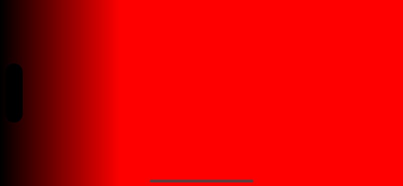
It looks like we get a nice red gradient effect… but it seems to go flat partway across the screen.
That’s because position.x/255.0 begins at zero, then happily increases by the x position of each pixel. Once the shader gets 255 pixels along, position.x/255.0 resolves to 1.0, which is plain red. The max value of the red component is 1.0, so everything past 255 pixels stays red.
Modulating the red component of color by x position
Next, let’s try playing with the vertical (y) component, and modify another of the RGB values:
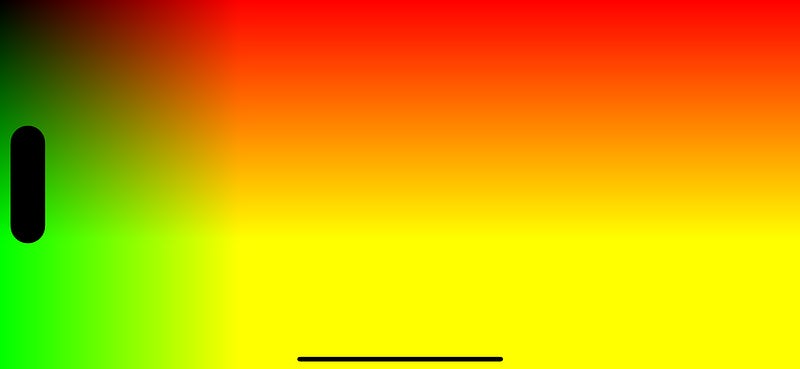
Now, we yield a much cooler-looking gradient, which modulates both horizontally and vertically.
Modulating the red and green components of color by x and y position, respectively
This is cool to look at, but quite wonky, and not exactly something we could use in our apps. It’ll also look very different on different screen sizes due to the shader working with discrete numbers of pixels.
We need to evolve our approach to make this gradient more smooth.
Understanding Geometry
Now let’s discover how to pass the geometry of our views into our shader. If you’re a mathematically-oriented Labrador and immediately bounded to this section, you’re in luck . Here’s the commit hash that catches up with everything so far.
To make our colorEffect shader more smooth, and, vitally, to ensure the behaviour of full-screen shaders is similar on all screen sizes, we need to know the geometry of the view which we’re modifying.
To achieve this, we need to an updated view modifier. The new visualEffect modifier is designed to give access to layout information such as size, so we can utilise it here.
We’re now using size as an argument in our shader. Since it’s two-dimensional information, it’s stored as a float2.
Of course, let’s not forget to adjust the modifier attached to our ContentView:
struct ContentView: View {
    var body: some View {
        Color.white
            .edgesIgnoringSafeArea(.all)
            .sizeAwareColorShader()
    }
}
Our new shader function has the standard colorEffect args, plus the new size argument to play with. Let’s start by upgrading our original red gradient:
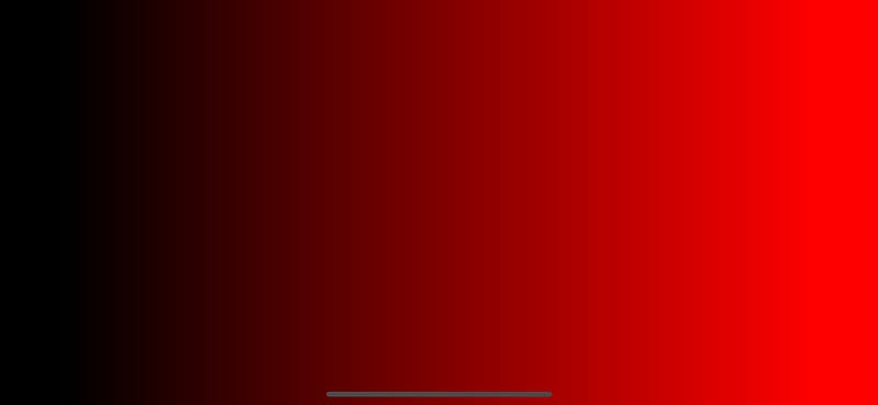
Red gradient produced by modulating the red color component with relative horizontal position
The position.x/size.x calculation does the heavy lifting here. For the less mathematically-oriented, this means that each pixel’s red color component is calculated by its relative horizontal position on-screen. For example:
For positions where x=0, the red component is 0, giving us a black color along the leading edge.
For positions where x=500, if the full horizontal size of the view is 1000 pixels, then position.x/size.x gives us 500/1000 which equals 0.5. This is the dark red in the middle of the screen.
For positions where x is equal to the full horizontal size , that is, the trailing edge, then position.x/size.x is just 1, giving the full red color.
Things become more complex comes when taking multiple color components across multiple dimensions, like so:
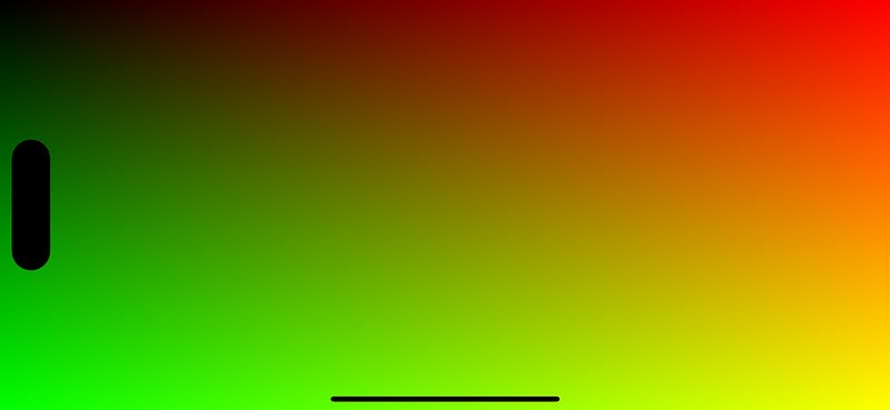
Red and green gradient created by smoothly modulating R and G values with relative position
Now the red color component varies horizontally, and the green color component varies vertically. As you can see, the key to learning shaders is taking a simple mathematical effect and layering on more complexity, bit by bit.
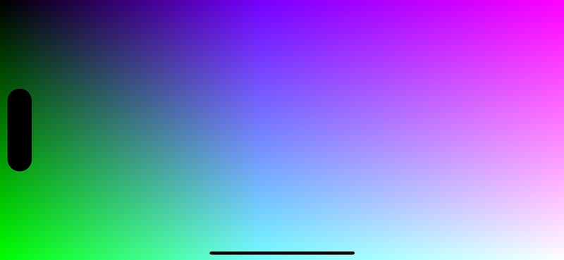
Now it’s time to have some fun with it. I felt bad we were leaving out the blue color component, so created this pleasing pastel effect:
Red, green, and blue gradient created by modulating RGB color values with position and size.
Seriously, please take some time to play with the shader yourself , finding the fun is the best way to learn.
Next, we’re going to ratchet up the complexity . Bear with me though, because this part is really critical to producing great shader effects.
Understanding Time
We’re about to bring some dynamism to our graphics shaders by transforming their outputs over time. If you yourself are a time traveller, and missed the last few sections, you can hit the ground running with this commit hash.
In order to vary our effects with time, we need to pass “time” as an argument into the shader function.
iOS handily introduced the TimelineView in iOS 15 to allow us to schedule view updates . We can initialise it with the .animation schedule to tell the system to re-evaluate the view very frequently.
extension View {
    func timeVaryingShader() -> some View {
        modifier(TimeVaryingShader())
    }
}

struct TimeVaryingShader: ViewModifier {

    private let startDate = Date()

    func body(content: Content) -> some View {
        TimelineView(.animation) { _ in
            content.visualEffect { content, proxy in
                content
                    .colorEffect(
                        ShaderLibrary.timeVaryingColor(
                            .float2(proxy.size),
                            .float(startDate.timeIntervalSinceNow)
                        )
                    )
            }
        }
    }
}
Our view modifier now stores a property, created on initialisation: a Date, which, unless you are a 5-dimensional creature from space, continuously increases at a rate of one second per second. Handy! A time interval of startDate.timeIntervalSinceNow is added as another argument for our new timeVaryingColor shader.
Again, let’s adapt our ContentView to the new temporal reality:
struct ContentView: View {
    var body: some View {
        Color.white
            .edgesIgnoringSafeArea(.all)
            .timeVaryingColorShader()
    }
}
After all this, we can now write our shader function:
Now we have time in our shader. But how do we use it?
Understanding Oscillation
With our current setup (here’s the commit hash!), float time will gradually increase with the lifetime of our view. But that isn’t particularly useful on its own. Often, we want to create a cyclic, repeating pattern in our shaders.
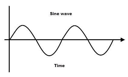
If you’ve blocked the memory of these bad boys out of your brain, that’s fine . While the mathematical underpinnings of trigonometric functions are fascinating; you only need to know that the sine of something creates a repeating pattern. Therefore, the function sin(time) will give you a value that smoothly oscillates between -1 and +1.
Before returning to our shader, let’s write a quick helper function:
This shifts the sine function so that instead of giving us -1 to +1, it returns 0 to 1. This is the right fit when we’re working with RGB components in color shaders, as their range of valid values is 0 to 1.
In shader lingo, this process is called normalisation and it makes numbers much easier to combine and transform.
One final thing before we use the time argument: we can actually illustrate this sine function with our gradient:
Here, we’re applying the sine function via oscillate. As per our original gradient, the position.x/size.x creates a series of values from 0 up to 1 horizontally. We’ve also scaled this by 2 * π (the constant for pi is M_PI_F), since that is the period of a sine function , the distance between each cycle.
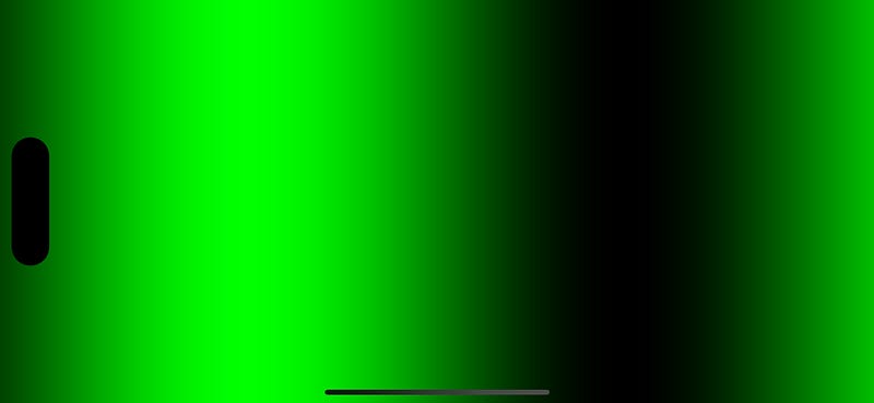
The result is a sine wave, in gradient form!
Drawing a sine wave using a green gradient
Project: Creating Disco Lights
We’ve been working through many of the fundamental concepts for using Metal in SwiftUI apps. We’ve learned how to use colorEffect to specify the color we want at each pixel position. We’ve built gradients and used geometry to fit them to our view.
We’ve even utilised the passing of time to transform our shaders, and utilised mathematical functions to display a static oscillation. Let’s merge these concepts at last, and design a shader which oscillates over time. Here’s the initial commit hash you can start from.
Let’s upgrade our timeVaryingColor shader with a time argument. We can use this as a factor in our oscillator function argument which contains our sine wave, to ensure the ever-increasing time number is clamped by the oscillation.
Now, we can start having fun with it, playing with the numbers and the speed of oscillation in each RGB value. I won’t go too deep into it, because these gifs are a pain in the arse to generate, but here’s where I ended up:
This more complex function produces slightly different oscillations for all 3 RGB values, resulting in this generous hit of acid:
Disco lights effect created with my timeVaryingColor shader
Morphing rainbows bring us to the logical conclusion of colorEffect for now. Let’s look at the next modifier bestowed upon us by iOS 17: distortionEffect.
Part III: Distortion Effect
Understanding Distortion
The distortionEffect modifier applies a “geometric distortion” effect on the location of each pixel. Much like its cousin colorEffect, the shader runs on each pixel, using pixel location as an argument. If you just skipped ahead to learn about distortion, here’s the commit hash you can start from.
Instead of outputting a half4 color, the distortion shader returns a float2 position vector, as the whole idea is to modify the location of our pixels.
Let’s distort a simple SFSymbol with a new custom view modifier.
struct ContentView: View {
    var body: some View {
        Image(systemName: "globe")
            .font(.system(size: 200))
            .distortionShader()
    }
}
Our initial view modifier should look quite familiar, except we’re using a distortionEffect now, which takes a maxSampleOffset property. We’ll discuss this momentarily.
By applying padding, we give the view some horizontal space around itself, increasing its drawable area. The drawingGroup modifier flattens the render tree of the padded image into a single raster layer, so that the distortionEffect applies to the whole thing (otherwise it ignores the padding).
maxSampleOffset warns SwiftUI that the shader function will try to offset the pixels from their original location. Annoyingly, you’d think the maxSampleOffset property would suffice on its own; but ho hum.
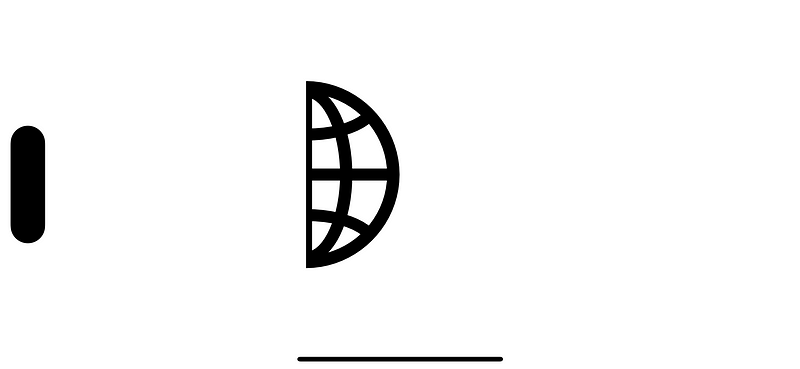
With all that setup out of the way; now we’ve achieved our heart’s desire: an intact image; horizontally offset.
Now we understand the basics of how to wrangle the distortionEffect modifier, we can start to work out what is happening on a pixel-by-pixel level. Here’s the commit hash if you’re starting fresh from here.
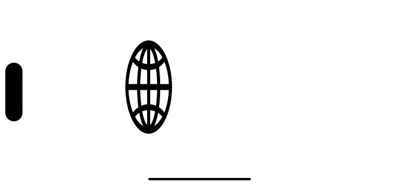
Now we’re all on the same page, we can play around with our distortion shader, compressing or stretching the image like so:
If you play around with it yourself, you may notice something counterintuitive:
position.x + 100shifts the image to the left instead of right.
position.x * 2 compresses the image instead of stretching.
Why are these shaders working “backwards”?
The answer makes sense when you understand how the shader is actually working. The shader needs to work out what to render in each pixel of the screen.
To achieve this, the function declaration takes the argument float2 position, the position of the destination pixel on the screen. The output float2 is the coordinate of the source pixel, the pixel from which the distortion effect at the destination renders.
By running the function this way around, no unnecessary work is done . Only pixels that actually appear in the drawable area are evaluated.
struct ContentView: View {
    var body: some View {
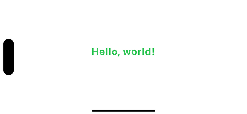
        Text("Hello, world!")
            .font(.largeTitle)
            .fontWeight(.bold)
            .kerning(2)
            .foregroundStyle(.green)
            .wigglyShader()
    }
}
Now we write the view modifier for the distortionEffect. It’s resplendent with all the bells and whistles (i.e. boilerplate) we defined before, plus a TimelineView and startDate property.
The padding and maxSampleOffset parameters are similar to before, except for the wiggle effect we’ll want to create a taller drawable area; using vertical offsets. As before, startDate is used to produce a time argument for our wiggly shader.
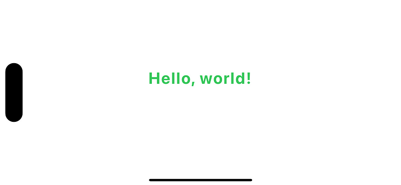
Let’s build up in phases again. First, our shader simply fetches pixels from the original position.
Text distortion effect : base case with identical source and destination pixels.
Let’s add a small adjustment with some oscillation . Here, we can simply use sin(time) because we can use positive and negative values. Let’s multiply the sine function by 10 so that the value goes from -10 to +10 instead of -1 to 1.
Here you can see the result : a gentle bounce up and down.
Text slightly vertically offset over time due to the distortion shader (build it yourself to see!)
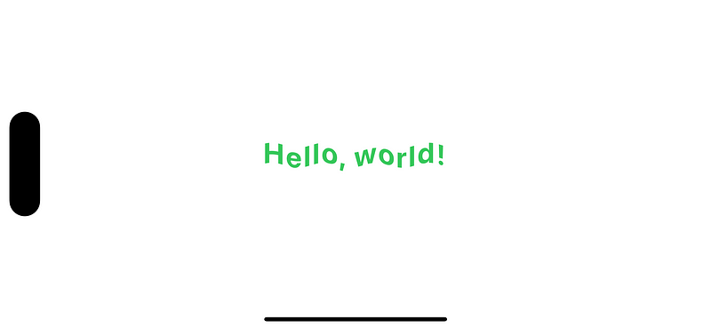
To add a little more pizzaz to our wiggle, the oscillation should vary horizontally. Therefore, we enter position.x into the sine function along with time.
A little more fiddling around, and now we’ve produced a beautiful wiggle effect, invoking classic 90’s WordArt.
The ultimate distortion effect: a WordArt-style text wiggle. Now I just need a clippy!
Distortion effects are a powerful tool once you understand how Metal is wiring up source and destination pixels. Let’s now look at the final, and most advanced, Metal modifier in iOS 17: layerEffect.
Part IV: Layer Effect
Understanding Layer Effect
layerEffect is the final type of Metal shader modifier added in iOS 17. They have more in common with colorEffect, but I left them for last because the behaviour is little tricky to wrap your head around.
Before breaking your brain with rasterisation theory; let’s quickly get our view modifiers out of the way. The globe SFSymbol is as good as any to use, but please use any image you like to establish a false sense of agency.
struct ContentView: View {
    var body: some View {
        Image(systemName: "globe")
            .font(.system(size: 200))
            .pixellationShader()
    }
}
We’re going to use a pixellation effect as the basis for understanding layerEffect and sampling behaviour. Now we just write the view modifier:
#include <metal_stdlib>
#include <SwiftUI/SwiftUI_Metal.h> // We'll talk about this in a minute!
using namespace metal;

[[ stitchable ]]
half4 pixellate(float2 position, SwiftUI::Layer layer) {
    return layer.sample(position);
}
Annnddd….. Not much.
Result of a layerEffect sampling the position without transformation
When we sample the layer at position of each pixel, this results in… the pixel itself. The view isn’t affected at all. Let’s look into Layer itself and find out what’s going on.
SwiftUI::Layer and Sampling
Introducing a shiny new type, in a shiny new module, SwiftUI::Layer simply retrieves the Layer type from the SwiftUI namespace.
If you remember from ~4000 words ago; namespaces help you keep your C++ modules clean and tidy: using namespace metal at the top of our shader file means we don’t need to call metal::float2 and metal::half4 everywhere. Frankly, I reckon it’s a better system than Objective-C’s approach of “prefix your classes and hope they don’t collide”.
Sampling is the special sauce that makes layerEffect different from the other shaders that use a paltry color or position. The extra import #include <SwiftUI/SwiftUI_Metal.h> contains a single type declaration, Layer, which contains a single pretty terse function, sample():
struct Layer {
  metal::texture2d<half> tex;
  float2 info[5];

  /// Samples the layer at `p`, in user-space coordinates,
  /// interpolating linearly between pixel values. Returns an RGBA
  /// pixel value, with color components premultipled by alpha (i.e.
  /// [R*A, G*A, B*A, A]), in the layer's working color space.
  half4 sample(float2 p) const {
    p = metal::fma(p.x, info[0], metal::fma(p.y, info[1], info[2]));
    p = metal::clamp(p, info[3], info[4]);
    return tex.sample(metal::sampler(metal::filter::linear), p);
  }
};
The Layer itself represents the raster layer of the SwiftUI view, which is being transformed by the shader. Metal generates a texture2d from the view , essentially a bitmap image, to be sampled.
This texture is sampled to return the color of the pixel at position p. If the position is between pixel locations, then this sample function returns the weighted average color of the neighbouring pixels.
Like much of the Metal framework, it becomes a little easier to understand when you play around with it.
Project: Creating a Retro Filter
Since getting Nintendo Switch Online and rediscovering Super-NES classics such as A Link to the Past and Super Metroid, I’m a little enamoured with the simplistic beauty of pixel art, or the power of a CRT screen effect to magically elevate the graphics.
Baby steps. We can copy our earlier distortion effect if we simply try to shift the pixels here, sampling the pixel color at 100 pixels to the right of each pixel in question.
This gives us, as before in the distortion effect, a cut-off, left-shifted image.
layerEffect sampling the color of pixels 100px to the right of each pixel position
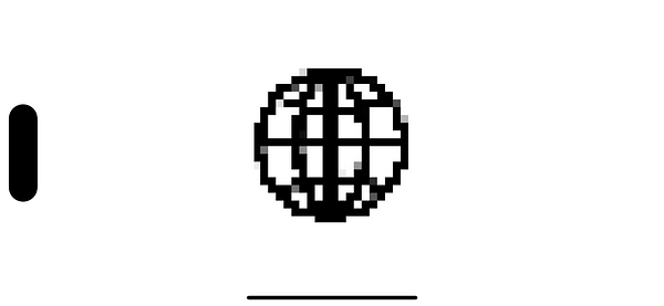
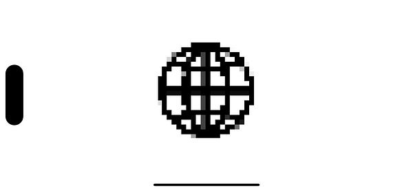
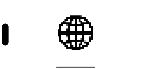
Now let’s use the sampling behaviour to pixellate our view. We’ll write a mathematical function in our shader to snap each pixel onto a grid where each gridline is spaced out by size. This maps the microscopic Super Retina XDR pixels into Minecraft-sized chunks.
Let’s elaborate on the maths through a worked example:
float sample_x = size * round(position.x / size);
Let’s take the pixels at x positions 0, 1, and 8. We’ll set size to 8 pixels.
Position 0:round(position.x / size) is just 0. Therefore multiplying by size also yields 0, so this pixel position will sample from x=0.
Position 1: round(position.x / size) is round(1/8) which rounds down to 0 . Therefore this position will also sample from x=0.
Position 8:round(position.x / size) is round(8/8), which equals round(1) or just 1. Multiplying the result by size 8, this samples a pixel from position x=8.
Extrapolating across every pixel location like this, we can see how we tell each square block of 8x8 pixels to all sample from the top-left pixel of the block.
The pixel size is configurable as an argument to our view extension:
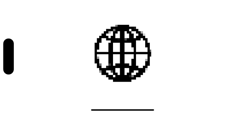
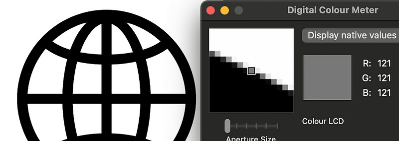
You might be wondering why there are grey pixels in our vector graphic. But if you zoom in, you’ll see that the whole edge of the image contains pixels at various gradations of grey.
This technique is known as anti-aliasing, and exists to give a smooth edge to an image : if we only used black and white, we’d see a jagged edge. Core Graphics itself is using its own sampling to blend edge pixels with the background color and render the 2D image on-screen.
Zoom into an image using Digital Color Meter (on MacOS) to demonstrate anti-aliasing
We can make things really interesting by introducing a time element to the modifier. Our final view modifier looks a little like this:
struct PixellationShader: ViewModifier {

    let pixelSize: Float
    let startDate = Date()

    func body(content: Content) -> some View {
        TimelineView(.animation) { _ in
            content
                .layerEffect(
                    ShaderLibrary.pixellate(
                        .float(pixelSize),
                        .float(startDate.timeIntervalSinceNow)
                    ), maxSampleOffset: .zero
                )
        }
    }
}
Now, our shader can use sin and cos functions to oscillate the x and y positions to and fro with time.
I’m a little ashamed to admit how long I spent staring at this.
Now we’ve learned the basics on how to write our own colorEffect, distortionEffect, and layerEffect . Now it’s time to run free. And learn how to tap into the wonderful world of pre-existing graphics shaders.
Part V: Flying Free
The Book of Shaders
This final chapter is more freeform. Since we’ve got the basics down, I’m just going to show the shaders : you should be able to set up your own view modifiers by now.
Online resources are our most important tool. You may be surprised (or not) to hear that shaders are a pretty universal concept, not monopolised by Apple and Metal. Shaders are found in games, on the web, and in animated films.
Therefore, there is a vast wealth of resources online and offline to demonstrate how to make more complex shaders, and knowing a few basics equips us with the keys to the kingdom.
The Book of Shaders uses OpenGL shading language. OpenGL is an open-source, universal, graphics framework which I’ve written about in my piece Through The Ages: Apple’s Animation APIs.
Converting from OpenGL shading language to Metal is pretty straightforward; for example they use vec2 instead of float2. Converting most examples is therefore quite trivial, but occasionally things such as converting mat4 invMat = inverse(mat) into float4x4 invMat = matrix_invert(mat) might require looking up some online references.
Random noise
A common shader effect is producing random noise, similar to the static you’d see on an old television set.